Z LED Frame, or how to illuminate your art with Zephyr - part 2: Zephyr, LEDs and networking
Warm welcome to you all after the long dark of wintry nights. I managed to get a couple of powder days (despite terribly dry spell this winter) and as I am writing this post my Prusa MK3S 3D Printer is doing brr rarely having any rest these days. In this blogpost we will focus on the core of the project which is serving an HTTP server over a Wi-Fi connection, receiving an image from the user, loading it to MCU’s memory and finally displaying it on the LED strip. As always, engineering misconceptions and errors are abound so be sure to learn from my mistakes 😁
This is the second part of the ZLED Frame series:
- First part - Project introduction and early prototyping
- Third part - Coming soon! - FreeCAD + 3D printing
- Fourth part - Coming soon! - Extras
Now have a nice early March Austrian sunset to accompany your reading:

Zephyr How-To and project set-up
We got so far without really digging into what exactly Zephyr is doing in this project. First of all, what is Zephyr? To me it has always been akin to a younger brother of Linux having equally strong virality and momentum but targeted more for embedded devices. The thing that really bought me is that you usually can get any off-the-shelf development board and it will work assuming the example is supported for this board(most of which are available for a plethora of devices). Compare that to installing dubious toolchains 🤨 or binaries accessible only after you sell your data, kidney and a cut on your profits 😄
(Yes I am biased towards proprietary software, why do you ask?) - no, but really? Licensed compiler??? - yes - companies do that, yes - you know the big names
I won’t go into details on how to obtain the code itself (come on, we are all grown-up here), rather I will point out my preferred ways of working with this project. I usually checkout the latest stable branch and optionally create a new branch for some modifications to the project’s code that might arise during hacking around. Always be sure to be working in the virtual environment in which west has all the paths and variables set up properly - refer to the official guide on how to set up that.
Since I am using an out-of-tree project structure basing on existing project repository where I specify overlays for my board, the best course of action for you is to follow my step. Trust me, this way you will probably save yourself from painful decoupling if you would like to move your project to be something bigger. What I don’t recommend though, is working outside the Zephyr’s virtual environment - don’t go this path of pain…
Once we have our project set up, we should create an app.overlay file with following contents:
/*
 * Copyright (c) 2024 Jakub Duchniewicz
 *
 * SPDX-License-Identifier: Apache-2.0
 */

#include <zephyr/dt-bindings/led/led.h>

&spi2 {
	/* Workaround to support WS2812 driver */
	line-idle-low;

        led_strip: ws2812@0 {
                compatible = "worldsemi,ws2812-spi";

                /* SPI */
                reg = <0>; /* ignored, but necessary for SPI bindings */
                spi-max-frequency = <6400000>;

                /* WS2812 */
                chain-length = <256>; /* arbitrary; change at will */
                spi-cpha;
                spi-one-frame = <0xf0>; /* 11110000: 625 ns high and 625 ns low */
                spi-zero-frame = <0xc0>; /* 11000000: 312.5 ns high and 937.5 ns low */
                color-mapping = <LED_COLOR_ID_GREEN
                                 LED_COLOR_ID_RED
                                 LED_COLOR_ID_BLUE>;
        };
};

$wifi {
    status = "okay";
};

/ {
        aliases {
                led-strip = &led_strip;
        };
};
In case you are not familiar with the Device Tree Structure files I recommend(as always) great Bootlin’s presentations that very concisely describe what’s what.
The overlay above initializes the SPI connected Data pin of the LED strip, enables the Wi-Fi and creates an alias for the LED strip node in the Device Tree. Overlays are special entities that are used to add or alter nodes of the Device Tree that are added during compilation. In our case we have a standalone ESP32-Wroom board that has some fixed peripherals and settings specified first in the SoC’s device tree file and then the board itself and we simply add additional external peripheral that we have to configure during compilation. (There have been recently some changes since Espressif introduced a new hardware model which I still need to go over - so expect me explaining that in a future post).
Assuming you want to use the same LED strip with ESP32 you will simply need to adjust the chain-length parameter at will.
Device tree is just one part of the configuration - we also need to add several basic config defines to augment those included in the default app:
CONFIG_LOG=y
CONFIG_SPI=y
CONFIG_LED_STRIP=y
CONFIG_WS2812_STRIP=y

## Copied over from the sample - to reduce
# POSIX options
CONFIG_POSIX_MAX_FDS=20

# Networking config
CONFIG_NETWORKING=y
CONFIG_NET_IPV4=y
CONFIG_NET_IPV6=n # it is set to yes either way
CONFIG_NET_TCP=y
CONFIG_NET_UDP=n
CONFIG_NET_SOCKETS=y
CONFIG_NET_SOCKETS_POSIX_NAMES=y
CONFIG_NET_MAX_CONN=20
CONFIG_NET_MAX_CONTEXTS=20
CONFIG_NET_STATISTICS=y
CONFIG_NET_CONNECTION_MANAGER=y

# Network buffers
CONFIG_NET_PKT_RX_COUNT=96
CONFIG_NET_PKT_TX_COUNT=96
CONFIG_NET_BUF_RX_COUNT=128
CONFIG_NET_BUF_TX_COUNT=128
CONFIG_NET_CONTEXT_NET_PKT_POOL=y
CONFIG_NET_BUF_POOL_USAGE=y

# IP address options
CONFIG_NET_IF_UNICAST_IPV6_ADDR_COUNT=3
CONFIG_NET_IF_MCAST_IPV6_ADDR_COUNT=4

# Network address config
CONFIG_NET_CONFIG_SETTINGS=y
CONFIG_NET_CONFIG_NEED_IPV4=y
CONFIG_NET_CONFIG_MY_IPV4_ADDR="192.168.0.230"
CONFIG_NET_CONFIG_PEER_IPV4_ADDR="192.168.0.231"
CONFIG_NET_CONFIG_NEED_IPV6=y
CONFIG_NET_CONFIG_MY_IPV6_ADDR="2001:db8::1"
CONFIG_NET_CONFIG_PEER_IPV6_ADDR="2001:db8::2"

# Network debug config
CONFIG_NET_LOG=y
CONFIG_NET_SHELL=y

# This is needed so that the sample app can respond to queries
# as fast as possible.
CONFIG_NET_TCP_TIME_WAIT_DELAY=0

# This is needed for Wi-Fi connections
CONFIG_NET_L2_WIFI_SHELL=y

CONFIG_ESP_HEAP_MEM_POOL_REGION_1_SIZE=1024
# is this necessary?
CONFIG_HEAP_MEM_POOL_SIZE=98304


## overlays for ESP32
CONFIG_WIFI=y
CONFIG_NET_L2_ETHERNET=y
CONFIG_NET_DHCPV4=y
CONFIG_ESP32_WIFI_STA_AUTO_DHCPV4=y
Most importantly, we need to enable logging, Wi-Fi, IPv4 capabilities, the WS2812 LED strip support, and change the CONFIG_ESP_HEAP_MEM_POOL_REGION_1_SIZE to be 1024 otherwise we will be hitting errors binary creation due to too small memory regions. Lastly, we need to set up the IPv4 address that we will be connecting to from our client (be careful not to overlap with any existing one on your local network).
Application logical split
Even though it is not a grand project, I would be neglecting my computer science background without partitioning it into encapsulated components, so here they are:
- main - self-explanatory, calls the interface functions and spawns threads
- pixels - arranging the pixels, creating frames and pushing them to the LED driver
- network - basing on the dumb_http_server sample, establishes the HTTP server and responds to API calls, also parses the incoming data and informs the
pixelsmodule that the data was obtained
As you can see it is really basic but allows us to freely add more components if we wish without cluttering the main file too much. Thread-wise we also don’t have much going on and we only need to synchronize the threads whenever a new image is provided over the network so that proper data is displayed on the screen.
Interfacing WS2812
As we have already seen above, we are using the LED strip containing the WS2812 LEDs having a very tiny datasheet. Even though the datasheet is tiny (and does not really tell us what is the factual power consumption of a single LED) it shows that we have just 3 wires, namely VCC(Voltage input), GND, and a Data in pin that is interfaced from our ESP.
The driver is also fairly simple, uses bit banging? (verify that) - we won’t go into details, and that’s also one thing that is so great about Zephyr - when you have drivers, it just works! When you don’t have the drivers, well then that’s a different story, but then usually you are experienced enough to at least tackle it on your own 😁
For the prototype I used a battery pack that initially supplied 6V (4 * 1.5V battery) so I had to use several voltage dropping diodes (those I had laying around were of the Schottky type so they had slightly lower voltage drop). One thing that I must warn you about when you would like to use such a battery pack is that the batteries yield lower voltage over time (as they discharge), so after several hours of debugging I stumbled into a very weird error: I could not turn the LEDs blue…
Dumb as it may sound, I was thinking that maybe there was a mistake in the driver or the hardware itself was faulty, only after several hours of digging around and learning about blue LED production difficulties - I realized that maybe the voltage is simply too low for the blue LED to light up. Removing several of the voltage dropping diodes solved the problem 🤦
There is a lesson in this for all of us - never trust your batteries 😁
After making sure the LEDs can shine in their entirety of the spectrum, one can start giving them something more lofty than just test patterns, but before we go into displaying images from memory, let’s go briefly over the code of how to interface them. As I said before the beauty of working with a full-fledged system is that you usually have most things abstracted in the form of API (as long as it works 😄)
In my case it was as simple as getting the device from the device tree, initializing it and calling led_strip_update_rgb with the data I want to display.
   #define STRIP_NODE DT_ALIAS(led_strip)

   static const struct device *const strip = DEVICE_DT_GET(STRIP_NODE);
Then we call a simple calibration routine:
int display_preset_pattern(const struct device *const strip)
{
    int rc;

    memset(&pixels, 0x00, sizeof(pixels));
    memcpy(&pixels[cursor], &colors[color], sizeof(struct led_rgb));
    rc = led_strip_update_rgb(strip, pixels, STRIP_NUM_PIXELS);

    if (rc)
    {
        return rc;
    }

    cursor++;
    if (cursor >= STRIP_NUM_PIXELS)
    {
        cursor = 0;
        color++;
        if (color == ARRAY_SIZE(colors))
        {
            color = 0;
        }
    }
    return 0;
}
My code is slightly more complex because I am running it in a thread and waiting for the data to arrive from the client and then I need to reverse the data as the LED is soldered in a snake pattern like in the below figure while the data is ordered sequentially in the memory buffer.
This can be also done on the client side to reduce the workload on the MCU 😁
int display_network_image(const struct device *const strip)
{
    int rc;

    // Wait for the semaphore indicating a new image is ready
    if (k_sem_take(&image_semaphore, K_NO_WAIT) == 0)
    {
        LOG_ERR("Received image - semaphore taken");
        //  Copy the received image to the pixels array
        memset(pixels, 0x00, sizeof(pixels));
        // convert pixel data to led_rgb
        size_t index = 0;
        for (int i = 0; i < STRIP_LINE_LENGTH; ++i)
        {
            for (int j = 0; j < STRIP_LINE_LENGTH; ++j)
            {
                // since the led strip is sequential, we have to reverse every second line
                if (i % 2 == 0)
                {
                    pixels[index] = RGB(received_image[index * 3], received_image[index * 3 + 1], received_image[index * 3 + 2]);
                }
                else
                {
                    size_t reversed_index = i * STRIP_LINE_LENGTH + STRIP_LINE_LENGTH - j - 1;
                    pixels[index] = RGB(received_image[reversed_index * 3], received_image[reversed_index * 3 + 1], received_image[reversed_index * 3 + 2]);
                }
                ++index;
            }
        }

        // Update the LED strip with the new image
        rc = led_strip_update_rgb(strip, pixels, STRIP_NUM_PIXELS);

        if (rc)
        {
            return rc;
        }
        LOG_ERR("Finished image drawing");
    }

    return 0;
As you can see the pixel displaying code is really simple, we will extend (and optimize 😄) it in the near future.
Networking primer
Networking-wise, the ESP works as a server - meaning that it provides the HTML + CSS + Javascript code needed to display the website on the client which may be your PC, mobile phone or even another microcontroller (of course assuming it has a browser capabilities). The server is running on the Wi-Fi network with a static IP so everyone on the network can access it (yes, it is not the most secure thing but since my network is fairly well isolated from the outside world I am not really afraid - besides it is not a drug injector). Also, implementing full network security is beyond this blogpost, but you are always encouraged to read up on it 😄.
When I connect to the server, I make a request to the root endpoint - / and the server transfers the binary blob containing the code to be run on the client. The HTML code is rendered by the browser and the Javascript code executes either immediately or when special action is undertaken (i.e) button press. The code runs on the client so we can leverage a more powerful machine to do our dirty data processing 😁
In our case we offload image pre-processing and massaging it to be a raw-byte array that we receive on the server via an API-call to the /api/image endpoint. There are some caveats that we have to consider when we are implementing networking ourselves - such as, parsing (or ignoring) message headers and knowing when we receive desired data.
Overall, the flow looks like that: (basic functionality for now)
Server Side
We talked high-level so let’s now get more concrete and see how it is implemented in code. Everything starts by spawning a thread for TCP IPv4 processing (somehow I got weird crashes when not enabling IPv6) - this thread creates a BSD socket that will be used as a high-level abstraction for communication with the client.
static void process_tcp4(void)
{
	struct sockaddr_in addr4;
	int ret;

	(void)memset(&addr4, 0, sizeof(addr4));
	addr4.sin_family = AF_INET;
	addr4.sin_port = htons(MY_PORT);

	ret = setup(&tcp4_listen_sock, (struct sockaddr *)&addr4,
				sizeof(addr4));
	if (ret < 0)
	{
		return;
	}

	LOG_DBG("Waiting for IPv4 HTTP connections on port %d, sock %d",
			MY_PORT, tcp4_listen_sock);

	while (ret == 0 || !want_to_quit)
	{
		ret = process_tcp(&tcp4_listen_sock, tcp4_accepted);
		if (ret < 0)
		{
			return;
		}
	}
}
Then we accept and create a thread for receiving the data:
static int process_tcp(int *sock, int *accepted)
{
	static int counter;
	int client;
	int slot;
	struct sockaddr_in6 client_addr;
	socklen_t client_addr_len = sizeof(client_addr);

	client = accept(*sock, (struct sockaddr *)&client_addr,
					&client_addr_len);

	/* ommited */

#if defined(CONFIG_NET_IPV4)
	if (client_addr.sin6_family == AF_INET)
	{
		tcp4_handler_tid[slot] = k_thread_create(
			&tcp4_handler_thread[slot],
			tcp4_handler_stack[slot],
			K_THREAD_STACK_SIZEOF(tcp4_handler_stack[slot]),
			client_conn_handler,
			INT_TO_POINTER(slot),
			&accepted[slot],
			&tcp4_handler_tid[slot],
			THREAD_PRIORITY,
			0, K_NO_WAIT);
	}
#endif

	if (LOG_LEVEL >= LOG_LEVEL_DBG)
	{
		char addr_str[INET6_ADDRSTRLEN];

		net_addr_ntop(client_addr.sin6_family,
					  &client_addr.sin6_addr,
					  addr_str, sizeof(addr_str));

		LOG_DBG("[%d] Connection #%d from %s",
				client, ++counter,
				addr_str);
	}

	return 0;
}
Then whenever a request is made we read the data from the socket using the recv API and then match the received endpoint against the list of allowed endpoints (that we specify) - note the parse_header trick I added as the recv reads data in batches and we might have already read the header of the request. It is probably not the most robust way of doing things but for my limited application it works just fine.
static void client_conn_handler(void *ptr1, void *ptr2, void *ptr3)
{
	ARG_UNUSED(ptr1);
	int *sock = ptr2;
	k_tid_t *in_use = ptr3;
	int client;
	int received;
	int ret;
	char buf[RECEIVE_BUF_LEN];

	char endpoint_buf[20];
	bool parsed_header = false;
	method_t method;

	client = *sock;

	do
	{
		received = recv(client, buf, sizeof(buf), 0);

		if (received == 0)
		{
			/* Connection closed */
			LOG_DBG("[%d] Connection closed by peer", client);
			break;
		}
		else if (received < 0)
		{
			/* Socket error */
			ret = -errno;
			LOG_ERR("[%d] Connection error %d", client, ret);
			break;
		}

		LOG_DBG("[%d] Received data: %.*s", client, received, buf);

		if (!parsed_header)
		{
			if (parse_header(buf, sizeof(buf), endpoint_buf, sizeof(endpoint_buf), &method) != 0)
			{
				LOG_ERR("[%d] Could not parse header", client);
				break;
			}
			parsed_header = true;
		}

		if (handle_endpoint(client, endpoint_buf, method, buf, RECEIVE_BUF_LEN) == 0)
		{
			LOG_ERR("Handled the endpoint - exiting.");
			break;
		}
	} while (true);

	(void)close(client);

	*sock = -1;
	*in_use = NULL;
}
We first parse_header and allow only ones that we desire - note that this is a VERY incomplete HTTP server 😁
static int parse_header(char *buf, int buf_size, char *endpoint, int endpoint_size, method_t *method)
{
	char *ptr = buf, *delim_pos = NULL;
	int len = 0;
	if (strstr(ptr, "GET"))
	{
		*method = GET;
		ptr += 4; // +1 for whitespace
	}
	else if (strstr(ptr, "POST"))
	{
		*method = POST;
		ptr += 5;
	}
	else
	{
		LOG_ERR("Unknown method found!");
		return -1;
	}

	delim_pos = strchr(ptr, ' ');
	len = delim_pos - ptr;
	if (len + 1 > endpoint_size)
	{
		LOG_ERR("Too long endpoint name! Max allowed: %d", endpoint_size);
		return -1;
	}

	strncpy(endpoint, ptr, len);
	*(endpoint + len) = '\0'; // null-terminate it

	LOG_DBG("Found method of type: %d with endpoint name: %s", *method, endpoint);

	return 0;
}
Then we handle the endpoint using handle_endpoint the function:
static endpoint_t valid_endpoints[NUMBER_OF_ENDPOINTS] = {
	{"/", GET}, // TODO :add handling for favicon :)
	{"/api/image", POST},
};

static int handle_endpoint(int client, char *endpoint_buf, method_t method, char *buf, int buf_len)
{
	//  GET /
	if (strncmp(valid_endpoints[0].name, endpoint_buf, strlen(endpoint_buf)) == 0)
	{
		// here we don't need to check any return values and can directly return the page to render
		LOG_ERR("Sending the data to the client!");
		(void)sendall(client, content, sizeof(content));
		return 0;
	}
	else if (strncmp(valid_endpoints[1].name, endpoint_buf, strlen(endpoint_buf)) == 0)
	{
		LOG_ERR("Handling POST /api/image");
		static bool read_header = false;
		uint8_t length = 0u;

		if (read_header)
		{
			LOG_ERR("rcv_img_offset + buf_len: %d MAX_IMAGE_SIZE: %d", rcv_img_offset + buf_len, MAX_IMAGE_SIZE);
			// for now this will inform that we handled all
			if (rcv_img_offset + buf_len >= MAX_IMAGE_SIZE)
			{
				LOG_ERR("Stop accepting - Trying to send more data than Image can accept.");
				length = MAX_IMAGE_SIZE - rcv_img_offset;
				if (length > 0)
				{
					// this contains raw binary data - 0 is null terminator there :)
					memcpy(received_image + rcv_img_offset, buf, length);
				}
				rcv_img_offset = 0;
				read_header = false;

				// Give the semaphore to notify that a new image is ready
				k_sem_give(&image_semaphore);

				// sleep a short amount so that the waiting thread can read the data
				k_sleep(K_MSEC(20));
				// Wait for the image to be processed
				k_sem_take(&image_semaphore, K_FOREVER);
				return 0;
			}

			memcpy(received_image + rcv_img_offset, buf, buf_len);

			rcv_img_offset += buf_len;
			return -1;
		}

		// until get the magic number, keep reading the header 0xBADAD00B
		// there is a slight chance that the magic number will be split between two packets - but for now we don't handle it
		char *pos = strstr(buf, magic_number);
		if (pos)
		{
			LOG_ERR("Found the magic number!");
			read_header = true;

			// read the remainder as the image data
			rcv_img_offset = 0;
			length = buf_len - (pos - buf) - strlen(magic_number);
			memcpy(received_image, pos + strlen(magic_number), length);
			rcv_img_offset += length;
		}
		LOG_ERR("Still parsing the header");
		return -1;
	}

	LOG_ERR("Unknown endpoint and header!");
	return 0;
}
You can see that this function is fairly long while not doing that much. The main issue here is that we need to handle each distinct API endpoint differently and also parse/ignore the header fields, I added a magic value of 0xBADAB00B to know when my desired payload begins. This magic value is added on the client side as well. Astute readers might note that the magic value might be split between two consecutive buffers - this will be fixed soon but for now we don’t really need to care as the header length is fixed - but it should be fixed nonetheless.
When the entirety of the image payload is read the semaphore is kicked and the image is displayed on the LED strip - you might say our job here is done 😁
Client Side
Client-wise we have a very basic HTML + CS + Javascript code. For now it is really basic, but we will put our frontend magic skills to use in a moment so let’s go over the full code in a future post. For now just a small snippet that downsamples the uploaded image and calls the /api/image endpoint:
function processImage() {
  var fileInput = document.getElementById('fileInput');

  // Check if a file is selected
  if (fileInput.files.length > 0) {
    var file = fileInput.files[0];

    // Read the file as a data URL
    var reader = new FileReader();
    reader.onload = function(event) {
      var dataURL = event.target.result;

      // Display the original image preview
      var originalPreview = document.getElementById('originalPreview');
      originalPreview.innerHTML = '<img src="' + dataURL + '" width="200" alt="Original Image"/>';

      // Create an image element
      var image = new Image();
      image.onload = function() {
        // Create a canvas element
        var canvas = document.createElement('canvas');
        canvas.width = 16;
        canvas.height = 16;
        var ctx = canvas.getContext('2d');

        // Draw the image onto the canvas (resizing it to 16x16)
        ctx.drawImage(image, 0, 0, 16, 16);

        // Get the pixel data from the canvas
        var imageData = ctx.getImageData(0, 0, 16, 16);
        var pixelData = imageData.data;
        console.log(pixelData);

        // Create a Uint8Array to store the raw binary data
        var binaryData = new Uint8Array(16 * 16 * 3);
        var newIdx = 0;
        for (var i = 0; i < pixelData.length; i += 4, newIdx += 3) {
          binaryData[newIdx] = pixelData[i];           // Red
          binaryData[newIdx + 1] = pixelData[i + 1];   // Green
          binaryData[newIdx + 2] = pixelData[i + 2];   // Blue
        }

        processedImage = binaryData;

        // Display the converted image preview
        var convertedPreview = document.getElementById('convertedPreview');
        convertedPreview.innerHTML = '<img src="' + canvas.toDataURL() + '" width="200" alt="Converted Image"/>';

        // Log the binary data to the console
        console.log('Binary Data:', binaryData);
      };

      // Set the image source to the data URL
      image.src = dataURL;
    };

    // Read the file as a data URL
    reader.readAsDataURL(file);
  } else {
    alert("Please select a file before processing.");
  }
}

function uploadProcessedData() {
  // Create a new Uint8Array to hold the combined data
  var combinedArray = new Uint8Array(processedImage.length + 8); // 8 bytes for the "BADAB00D" string

  // Set the first 8 bytes to the "BADAB00D" string
  var magicHeader = new TextEncoder().encode("BADAB00D");
  combinedArray.set(magicHeader, 0);

  // Set the remaining bytes to the processed image data
  combinedArray.set(processedImage, 8);

  // Create a binary blob from the combined data
  var blob = new Blob([combinedArray]);

  console.log('Sending image + magic:', combinedArray);

  // Add your server endpoint URL here
  var endpointUrl = '/api/image';

  // Upload data to server
  fetch(endpointUrl, {
    method: 'POST',
    body: blob,
    headers: {
      'Content-Type': 'application/octet-stream' // Specify the content type as binary
    }
  })
  .then(response => response.json())
  .then(data => {
    // Handle server response if needed
    console.log('Server response:', data);
  })
  .catch(error => {
    console.error('Error:', error);
  });
}
Please note that we convert the RGBA input array to RGB values (this was confusing me because I assumed the input was RGB not RGBA so imagine the rubbish I got on the output - and even displayed!). Also, you can see that we are prepending the magic value of BADAB00D so that we may know when we receive the payload.
Closing thoughts
We have covered most important code that powers this project, still, in a future post I will go over several other additions to this project, such as animations and prettifying the UI. The aim of this blogpost series is for you to understand the most important concepts and be able to follow through by yourself - all code and design files are on GitHub so all you really need is to follow my tracks and maybe build something even better 😄
Next up, me learning FreeCAD, discovering yet again that I hate when programmers think cryptic error messages help anyone, 3D printing, re-calibrating my 3D printer, fighting with first-layer adhesion issues and then 3D printing again so stay tuned 😁
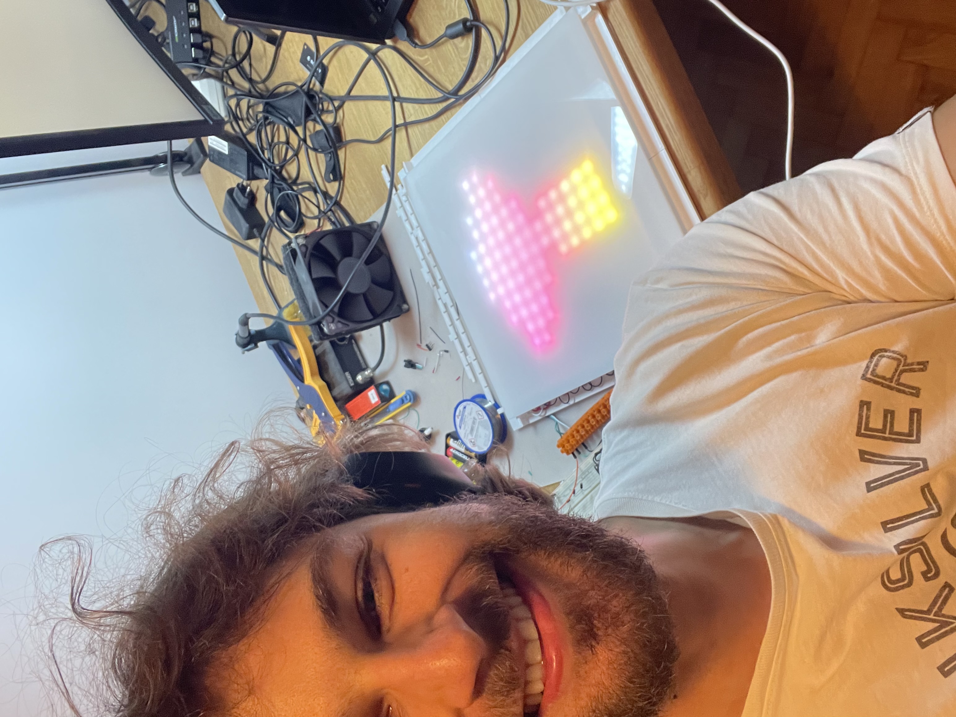
I am leaving you with a picture of my happy face with something working after I assembled and resoldered it:
Until later! (Yes I know that 2 weeks between blogposts is not feasible - probably one per month is the most often I can)
3841 Words
2024-03-27 18:12 +0000